A Double Fairlie in 16mm scale
By Don Boreham.
Those of our readers who were at the Keen House Open Day will have seen my new, as yet unfinished and unpainted, Double Fairlie which, in spite of its incompleteness, is quite capable of hauling a train - at least, on the MRC's test tracks which are complete ovals with one electrical section each and no pointwork.
Apart from making a D.F. body in card in 4mm scale many years ago, which hardly counts, I had never attempted such a machine before and was: aware that its construction would pose for me problems not usually met with in railway modelling. One of them, in passing, is the fact that the footplate is not level throughout thus necessitating a wooden flooring with a hole in the middle to accommodate the central low level, the whole being jacked up on wood blocks screwed to the underside at the ends. Build the model on this.
A much more important difficulty lies in the fact that basically a model Double Fairlie consists of two independent motor bogies suspended from the bodywork which serves as a connection between them. See fig.1
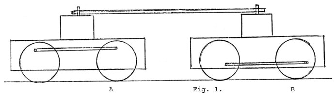
In this rough diagram the connecting bar represents the body. The actual fixing point is quite high since the pivot has to be arranged to clear the motors (not shown on the diagram but actually pointing inwards as there was more space for maneuver with them arranged in that position).
I was anxious to run the model at our Open Day and did so in the condition sketched above. Having tested it out previously at Keen House I knew that it would be safe to run it but I also knew that it would not be safe to run the model for long in that condition; and that for two reasons, one electrical, one mechanical.
Taking the electrical one first, the two bogies were electrically independent. This scarcely mattered at Keen House but on a layout this could have odd consequences; for if one half ran on to a dead section it would stop there as the rear half would still go on running! (Also, by the way, when wiring up each bogie you have to be careful to see that they are both wired the same way round — otherwise you are likely to get the same effect as F.W. Webb did on his uncoupled locos where the driving wheels where liable to revolve in opposite directions. There's a prototype for everything). Even without going to such extremes, if one half hesitated as a result of bad contact or dirty rails; the following half would also hesitate when it, in its turn, reached the unsatisfactory spot.
The cure for this is quite simple — just connect the two bogies electrically. This smooths matters considerably and is in accordance with Boreham's Law which states that all the wheels on a locomotive, without exception, should be available to supply current to each and every motor; and that, if there is a tender, these wheels should be used as well.
The mechanical problem is not quite so simply resolved. The pivotal point of each bogie is situated halfway between the coupled wheels and necessarily has to be well above them to clear the motor. It was pointed out by Nigel Macmillan, who visited me during the construction of the loco that this arrangement (fig.1) would invariably lead to derailments since it was impossible to produce two motors exactly evenly balanced, even though they were of the same make and type. The consequence would be that if, for example, the locomotive was traveling from A to B, if motor A was more powerful than motor B it would tend to push the latter and this, in its turn would cause the rear wheels of motor B to rise and derail. At the same time the rear wheels of motor A would also tend to rise. If the position were reversed so that B was more powerful than A then the front wheels of each bogie would tend to rise. In either case derailments were likely, especially (as I found by experiment) at points.
It was obvious that a good deal of thought would have to be given to this problem so I duly cogitated and came up with a solution. This would have consisted of the fitting of a bar below the bogies, pivoted in exactly the same relative positions as the upper one (the body, that is). The difficulty here would have been that owing to a certain amount of slackness, necessary to allow the bogies to swing, the tendency to tip up would still have been present and would by no means have been eradicated; also the practical difficulty of fitting a coupling bar among the bits and pieces already present - such as gear wheels, motor fixing, wires, and general bits and pieces - would have been practically insurmountable. So that was no good.
At this point the Open Day at Keen House was held and among the visitors was one Colin Binnie who, having come up from Wells stayed overnight at my house. I put the problem to him, and, as you will have already guessed, he came up with the solution.
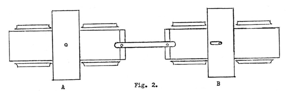
What this solution was will be seen from fig.2 which is seen in plan view (the cross-members, not shown in fig.1 are actually those attached to the bodywork which, again, is not illustrated). All you have to do is to attach a bar across the rear frame-spacers, allowing it to swing as the loco traverses a curve, and, at the same time opening out one of the pivot pin holes into a slot, pointing rearwards, into the interior of the loco. This combination allows the bogies complete freedom to swing round curves, while at the same time it prevents any wheels, front or rear, from riding up.
I was anxious to run the model at our Open Day and did so in the condition sketched above. Having tested it out previously at Keen House I knew that it would be safe to run it but I also knew that it would not be safe to run the model for long in that condition; and that for two reasons, one electrical, one mechanical.
Taking the electrical one first, the two bogies were electrically independent. This scarcely mattered at Keen House but on a layout this could have odd consequences; for if one half ran on to a dead section it would stop there as the rear half would still go on running! (Also, by the way, when wiring up each bogie you have to be careful to see that they are both wired the same way round — otherwise you are likely to get the same effect as F.W. Webb did on his uncoupled locos where the driving wheels where liable to revolve in opposite directions. There's a prototype for everything). Even without going to such extremes, if one half hesitated as a result of bad contact or dirty rails; the following half would also hesitate when it, in its turn, reached the unsatisfactory spot.
The cure for this is quite simple — just connect the two bogies electrically. This smooths matters considerably and is in accordance with Boreham's Law which states that all the wheels on a locomotive, without exception, should be available to supply current to each and every motor; and that, if there is a tender, these wheels should be used as well.
The mechanical problem is not quite so simply resolved. The pivotal point of each bogie is situated halfway between the coupled wheels and necessarily has to be well above them to clear the motor. It was pointed out by Nigel Macmillan, who visited me during the construction of the loco that this arrangement (fig.1) would invariably lead to derailments since it was impossible to produce two motors exactly evenly balanced, even though they were of the same make and type. The consequence would be that if, for example, the locomotive was traveling from A to B, if motor A was more powerful than motor B it would tend to push the latter and this, in its turn would cause the rear wheels of motor B to rise and derail. At the same time the rear wheels of motor A would also tend to rise. If the position were reversed so that B was more powerful than A then the front wheels of each bogie would tend to rise. In either case derailments were likely, especially (as I found by experiment) at points.
It was obvious that a good deal of thought would have to be given to this problem so I duly cogitated and came up with a solution. This would have consisted of the fitting of a bar below the bogies, pivoted in exactly the same relative positions as the upper one (the body, that is). The difficulty here would have been that owing to a certain amount of slackness, necessary to allow the bogies to swing, the tendency to tip up would still have been present and would by no means have been eradicated; also the practical difficulty of fitting a coupling bar among the bits and pieces already present - such as gear wheels, motor fixing, wires, and general bits and pieces - would have been practically insurmountable. So that was no good.
At this point the Open Day at Keen House was held and among the visitors was one Colin Binnie who, having come up from Wells stayed overnight at my house. I put the problem to him, and, as you will have already guessed, he came up with the solution.
What this solution was will be seen from fig.2 which is seen in plan view (the cross-members, not shown in fig.1 are actually those attached to the bodywork which, again, is not illustrated). All you have to do is to attach a bar across the rear frame-spacers, allowing it to swing as the loco traverses a curve, and, at the same time opening out one of the pivot pin holes into a slot, pointing rearwards, into the interior of the loco. This combination allows the bogies complete freedom to swing round curves, while at the same time it prevents any wheels, front or rear, from riding up.
I know this is so because I installed this system. It works, and I pass it on to anyone interested in. building a Doable Fairlie.
Before closing, let me add a postscript to the account of the Open Day. I forgot to mention that at Keen House that day was a steam-driven, radio-controlled loco. I had heard of this system but had never seen it in operation, although I have seen steam controlled with 2-rail electric control. Some very interesting results were obtained and I recommend the idea to any interested steam operator. It seems simple, effective, and easy to install.
D.A.B.