Cerrobond Casting Part II
By Bill Coffey.
While clay can be pressed into the resultant can, it has been found to be easier to work if the clay (toy shop Plasticine) is melted and poured into the can. The can should be filled with clay so that the upper surface is even with the tape and spacers. Set aside until the clay is completely hardened. While this is occurring lay out a circle on paper of the proper diameter and lay the patterns in place to determine the proper spacing. Attempt to balance relative part mass by distributing the equal sized parts diametrically opposite. ron't forget to provide space for the tie down bolts and spacers. At the same time fabricate a pouring sprue blank equal to the diameter and a length of one-half mold thickness plus 1/16". Using the relative plan devised on the paper circle, start embedding the patterns to their parting lines in the clay. Be very careful to obtain sharp parting lines between the clay and the pattern. The success of the mould may depend entirely upon the care taken at this time. When all of the patterns are in place in the clay, slide the bolts through the bottom plywood and the spacers. Place another set of spacers on the upper ends of the bolts. Thus there are now spacers equal to the full thickness of the mould. Using rubber cement, glue the pouring sprue to the under side of the top plywood in the exact centre. Allow to dry for a few minutes and then slide the top plywood over the bolts. Press down until the plywood is bottomed out against the spacers. Now remove the top plywood, upper spacers and bolts. Peel off the tape can wrapper. An impression will now be in the clay where the pouring gate blank is to be positioned. Remove the pouring gate blank from the top plywood with lacquer thinner and position in the proper position on the clay. Sprues can now be cut and installed from the part to the pouring gate blank. The end of the sprue that butts against the part or the pattern should be turned to a long taper. This permits the break off of the part from the sprue with little clean up. If the opening from the sprue to the part later proves to be too small, it can be opened up with a razor blade or knife. The upper mould half should now be ready to pour. Check once again that all patterns, sprues and gate are firmly seated into the clay to the parting lines with clean lines. Replace the bolts through the bottom plywood, spacers, add upper spacers and top plywood. Wrap the two plywoods with gummed paper tape and set aside. Staple to the bottom plywood and remove the top plywood. Once again we have an open top can with tape sides and a clay bottom (with patterns, sprues and a gate protruding), with the three bolts with spacers also protruding. See drawing step#1.
Now is the time for rubber. The choice of rubber and the mix formula is left to the individual choice, however after two years of working with the various types, I recommend General Electric RTV-60 as a general purpose molding rubber. The RTV-11 is excellent for some items and surface coatings. In the United Kingdom these are obtainable in small quantities from: Hermetite Limited, Tavistock Road, West Drayton, Middx. UB11 1RQ. Telephone: West Drayton (81) 45511. Prices: RTV-60 121bs. for £42-51 + VAT, 11b. for £4-43 + VAT;-11 11b. for £4-97 + VAT.Delivery is by Post or National Carriers, whichever is more expedient. Technical queries on the RTV's should be referred to: International General Electric Of America (positively no relation of British General Electric), Silicon Products Division, Bolton, Lancashire. Telephone: 0204 692 531. For suppliers in the U.S.A. try 'Yellow Pages' or most of the hobby mail order electronics suppliers.
The rubber must be weighed very accurately in order to determine the proper amount of catalyst to be added. The best results that I have experienced uses 5 drops of the Thermolite-12 (furnished with the RTV-60) to an ounce of rubber. The medicine dropper furnished with the RTV is used to assure even drop sizes. The proper amount of rubber is placed in a disposable container, weighed and the catalyst thoroughly mixed. If a vacuum pot is available, vacuum the mix to remove all air bubbles. These bubbles are so small that they cannot be detected, however they affect the mould. The vacuuming increases the amount of rubber space required by a factor of four so be sure that an adequate sized container is used. The rubber will foam up and then return to it's original position as the bubbles burst. A common pressure cooker can be hooked to the intake of an air compressor. This will usually provide sufficient vacuum to destroy most bubbles. If a vacuum is not available, use care in mixing to prevent excessive air induction, let set for a few minutes and break what bubbles do arise to the surface. The rubber will remain fluid for a considerable period of time, however work fast in all operations.
Using an ordinary clean water colour brush, paint all patterns and the clay surface with a thin coat of rubber, being sure to thoroughly work into all surface detail and holes. It will tend to settle out and cover, but sometimes air will be trapped and must be worked out especially on intricate surface details. Once the surface is completely covered and has settled, the remainder of the rubber can be poured. Pour a sufficient quantity to bring the level up to the top of the spacers and the pouring gate. Add a slight amount more spread evenly over the surface. Allow to set for about one half an hour, breaking all bubbles as they appear on the surface. The entire mould can be vacuumed, however care must be taken to prevent over foam. Install the top plywood over the bolts and inside the tape band. Place nuts on the bolts and tighten until the spacers are tight against the upper plywood. See drawing step*2. You will have a slight amount of excess rubber squeezed out through various openings and cracks. Actually you are applying pressure to the rubber which does two things. First the pressure causes the remaining air bubbles to be decreased in size and secondly forces the rubber tight up against the patterns. Set aside for at least twenty-four hours. This is longer than required but remember that haste makes waste, so regardless of how much you want to get on,'be patient.
TWENTY-FOUR HOURS LATER remove the tape from the sides of the mould, loosen and remove the three bolts. The plywood should peel from the rubber surface. Be careful not to disturb the patterns any more than possible. Now peel the rubber disc from the plywood and clay. Some of the patterns will stick in the clay and some will remain on the rubber. Clean all the clay from the rubber surface and trim any rubber leakage. Clean the patterns and re-install them in the rubber half, refitting them in the same locations with the rubber tightly against the patterns. Replace all the sprues in the exact location in the rubber that they occupied during the pouring of the first half. The pouring gate will probably remain in the rubber, but if it does not, carefully reinstall. Now we have to work upside down. Place the top plywood upside down with the holes through it. Carefully reinstall the rubber disc over the bolts. The spacers should have remained in the rubber disc. Place a second set of spacers on the bolts and install the bottom plywood in its original position. Again make the sides of the can from tape, stapling to the top plywood which is now on the bottom. When completed remove the bottom plywood (which is on the top) and check to see that none of the patterns have been disturbed in the rubber. See drawing step #A3.
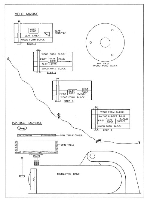
We must now apply a parting agent to the first half of the rubber mould in order to permit the pouring of the second half. Some RTV manufacturers recommend a 5% mixture of common household detergent such as 'Fairy Liquid' (U.S.A.: 'Joy'), mixed with water, while others recommend a grease type parting agent. The only thing I have found usable and easily applied is an aerosol spray of Teflon applied in a very thin coat over the rubber and patterns. For the U.K. try 1Klingerflon P2FE Aerosol Spray', obtainable in 14 oz. tins for €1-22i + VAT + post & packing from: Richard Klinger Ltd, Sidcup, Kent (Telephone: 01-300 7777). In the U.S.A. a similar product called 'Flour-Glide' is made by Chem Plast Corp. of New Jersey. Spray the entire rubber mould face and the patterns with a very light coat. It will disappear into the rubber but it is there. Excessive amounts will cause trouble and if it can be seen as a complete white coating, you have over sprayed. Pour the second half using the same techniques and procedures used in the first half. See drawing step #4.
let cure a sufficient amount of time, then separate. The patterns, sprues and gate can now be removed and a close examination of the mould halves made. Slight trimming in the gate-sprue area may be necessary due to rubber flow. Be careful not to cut into the pattern recess. The mould becomes stronger as it ages over about a week, but as with most modelers a trial shot will rapidly be attempted. A brief discussion of the spin table and drive is required prior to further work.
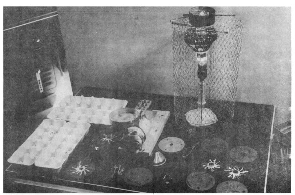
CASTING MACHINE. Any motor unit can be used as a drive, however the RPM of the spin table must be limited to prevent the centrifugal force from forcing the metal between the mould halves. After investigating several setups and systems it was decided that the simplest would probably be the best. An old Kenwood 'Cheffette' (U.S.A.: 'Mixmaster') was located with a burned out speed control. This was adapted for use by replacing the variable speed control with a set of fixed resistors to give three speeds. The really lazy amongst you could use a Philips 'Type HM 3060' hand-held food mixer straight from the box. For most operations, at least with a four inch diameter mould, full speed will give proper filling of the mould. The other speeds will be used with larger molds or with larger parts.
The spin table is a four inch, inside diameter, aluminium can fitted with a drive for the 'Cheffette'. The shaft is a bolt with the head removed and a slot ground in the side to engage the ball in the 'Cheff-ette' drive. A cover plate with a central pouring hole is required to fit inside the can. The spin table and the cover are drilled to the same hole pattern as used in the plywood form blocks. The cover is required to prevent the mould from separating ans spraying metal all over.
CASTING. Now you have a mould and a casting machine so lets make some castings. Melt down a pig of Cerro-Bend (don't get it too hot, but be sure that it is all melted, temperature should be 190 to 200 degrees), also put your ladle so that it will be heating up. Put the mould in the spin table, install the cover and snug up the bolts. Incidentaly the double spacers should be removed and a single installed so that it is between both mould halves. Well shall we give her a go? Turn on the motor and get the table up to speed. Using a small funnel pour in a spoonful of metal through the cover hole. Goofed already huh... too much metal so you threw a little. Well, that's something that you have to learn, how much metaal that the moulds will hold. Pouring fast will help molds to fill but you do take a chance of putting in an over abundance of metal. Right now would be a good time to put an open top wooden box around the casting machine to contain any metal overflow. It will happen from time to time. The mould should be set by now (a couple of minutes) so shut off the motor and after it has stopped remove the cover and remove the mould. lid you get some flash in the can? You must not have had the tie down tight enough. Again something that you can only learn by doing. Open the mould and let's see what you got. Probably only a partial fill or nothing in the sprues. Can be one of several things, but try another shot first because the mould has to heat up before it will shoot correctly. If it still does not work there is a possibility that you have tightened the tie down bolts too tight and have closed off the sprues feeding the parts. Try again not quite so tight. If this doesn't help but gives flash in the can between the mould halves, it would appear that the sprues are too small. Open them up a little. There are a couple of other things that can help to improve the filling of a mould. By placing the parts at a slight angle to the pouring gate to take advantage of the velocity of the direction of rotation, parts will fill better. Once in awhile a part just will not fill no matter what you do. This is usually an air lock. A knife cut from the part to the outside of the mould will usually cure this problem. The cut will permit the air to escape but not the metal. Now you should be getting parts but all of a sudden they look peculiar and if ignored, a few shots later will reveal that the metal is still molten in the mould after a normal spin period. The problem here is that the silicon rubber is a good insulator and consequently will absorb and retain the heat from the metal. Eventually it will get hot enough to have a slow metal chill and it's resultant large metal grain. If you don't let her cool of a bit, pretty soon the metal won't chill in the normal time period and when the mold is opened the metal runs out on the bench.
A couple of other items which may help out. By placing the deepest fill in the lower mould half, the air space in the upper mould is minimised with better filling. A coating of baby powder on the mould halves (shake off the excess) will give a matt appearance to the castings. Too much powder will contaminate the remelted metal however. You now have the basic ideas and you can carry it from here on your own. Lots of luck and have fun.
Editor's Note: This article first appeared in the September 1966 issue of 'FINEIINES', and is reprinted here by kind permission of Bob Brown, who now edits 'Finelines' successor: 'NARROW GAUGE AND SHORTLINE GAZETTE'. Part one was printed in 'MERCURY' No. 10.
let cure a sufficient amount of time, then separate. The patterns, sprues and gate can now be removed and a close examination of the mould halves made. Slight trimming in the gate-sprue area may be necessary due to rubber flow. Be careful not to cut into the pattern recess. The mould becomes stronger as it ages over about a week, but as with most modelers a trial shot will rapidly be attempted. A brief discussion of the spin table and drive is required prior to further work.
CASTING MACHINE. Any motor unit can be used as a drive, however the RPM of the spin table must be limited to prevent the centrifugal force from forcing the metal between the mould halves. After investigating several setups and systems it was decided that the simplest would probably be the best. An old Kenwood 'Cheffette' (U.S.A.: 'Mixmaster') was located with a burned out speed control. This was adapted for use by replacing the variable speed control with a set of fixed resistors to give three speeds. The really lazy amongst you could use a Philips 'Type HM 3060' hand-held food mixer straight from the box. For most operations, at least with a four inch diameter mould, full speed will give proper filling of the mould. The other speeds will be used with larger molds or with larger parts.
The spin table is a four inch, inside diameter, aluminium can fitted with a drive for the 'Cheffette'. The shaft is a bolt with the head removed and a slot ground in the side to engage the ball in the 'Cheff-ette' drive. A cover plate with a central pouring hole is required to fit inside the can. The spin table and the cover are drilled to the same hole pattern as used in the plywood form blocks. The cover is required to prevent the mould from separating ans spraying metal all over.
CASTING. Now you have a mould and a casting machine so lets make some castings. Melt down a pig of Cerro-Bend (don't get it too hot, but be sure that it is all melted, temperature should be 190 to 200 degrees), also put your ladle so that it will be heating up. Put the mould in the spin table, install the cover and snug up the bolts. Incidentaly the double spacers should be removed and a single installed so that it is between both mould halves. Well shall we give her a go? Turn on the motor and get the table up to speed. Using a small funnel pour in a spoonful of metal through the cover hole. Goofed already huh... too much metal so you threw a little. Well, that's something that you have to learn, how much metaal that the moulds will hold. Pouring fast will help molds to fill but you do take a chance of putting in an over abundance of metal. Right now would be a good time to put an open top wooden box around the casting machine to contain any metal overflow. It will happen from time to time. The mould should be set by now (a couple of minutes) so shut off the motor and after it has stopped remove the cover and remove the mould. lid you get some flash in the can? You must not have had the tie down tight enough. Again something that you can only learn by doing. Open the mould and let's see what you got. Probably only a partial fill or nothing in the sprues. Can be one of several things, but try another shot first because the mould has to heat up before it will shoot correctly. If it still does not work there is a possibility that you have tightened the tie down bolts too tight and have closed off the sprues feeding the parts. Try again not quite so tight. If this doesn't help but gives flash in the can between the mould halves, it would appear that the sprues are too small. Open them up a little. There are a couple of other things that can help to improve the filling of a mould. By placing the parts at a slight angle to the pouring gate to take advantage of the velocity of the direction of rotation, parts will fill better. Once in awhile a part just will not fill no matter what you do. This is usually an air lock. A knife cut from the part to the outside of the mould will usually cure this problem. The cut will permit the air to escape but not the metal. Now you should be getting parts but all of a sudden they look peculiar and if ignored, a few shots later will reveal that the metal is still molten in the mould after a normal spin period. The problem here is that the silicon rubber is a good insulator and consequently will absorb and retain the heat from the metal. Eventually it will get hot enough to have a slow metal chill and it's resultant large metal grain. If you don't let her cool of a bit, pretty soon the metal won't chill in the normal time period and when the mold is opened the metal runs out on the bench.
A couple of other items which may help out. By placing the deepest fill in the lower mould half, the air space in the upper mould is minimised with better filling. A coating of baby powder on the mould halves (shake off the excess) will give a matt appearance to the castings. Too much powder will contaminate the remelted metal however. You now have the basic ideas and you can carry it from here on your own. Lots of luck and have fun.
Editor's Note: This article first appeared in the September 1966 issue of 'FINEIINES', and is reprinted here by kind permission of Bob Brown, who now edits 'Finelines' successor: 'NARROW GAUGE AND SHORTLINE GAZETTE'. Part one was printed in 'MERCURY' No. 10.