It seems to me that there are two main types of modellers. The first consists of those noble souls who, having, while probably still in their cradles, chosen a scale, gauge and prototype line, stick to it rigidly, firmly eschewing all others. (Norman Eagles, he of the Sherwood section - a name not unknown to readers of this magazine - is an example of this sterling clan.)
The second type of modeller is somewhat less admirable, being more of a Dreadful Warning than a Shining Example. People of this type change their scale and gauge as the fancy takes them and any faded photograph of some old locomotive or piece of rolling-stock is enough to fire their wayward imagination, causing them to abandon what they are supposed to be doing and to go chasing after their new enthusiasm.
I regret to say that I am largely of the second type myself and, although I have tried my hardest to conform - even to the point of modelling the whole of the Campbeltown & Machrihanish Light Railway instead of getting on with the construction of the garden layout which had been planned down to the last detail, I suddenly found myself, in the summer of 1966, doing something quite different.
I have long been an admirer of large-scale narrow-gauge models (an interest which seems to be generally on the increase in the narrow-gauge world) and years ago made myself a promise to construct a sample train in a larger size than is usually used by railway modellers as distinct from model engineers; and when I read "Balloon Stacks & Sugar Cane", a fascinating book about the sugar cane railways in Fiji, I knew what that train would be - it would be a model of the Fiji Free Train, a 2ft. gauge conveyance run by the Colonial Sugar Refining Company, which owns most of the sugar-cane railways in Fiji, some of which are pretty extensive. The Free Train runs twice• a week or so, from its base at Lautoka to Kavarangaaau and back, a journey of about 80 miles in each direction. (On page 13 of B.S.&S.C. it is stated that this is the only free train service in the world but I think this is wrong. Isn't there at least one other, narrow gauge, of course, in Northern Spain?)
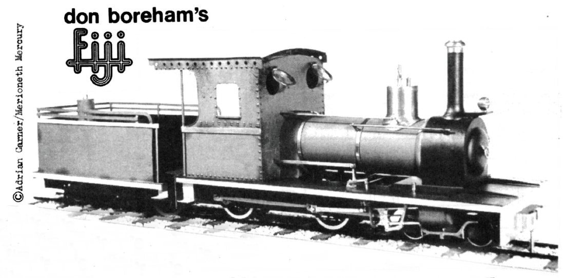
However, let us not quarrel with B.S.&S.C. since this is a valuable book for the modeller as it gives drawings of all the principal types of vehicles used in Fiji, locomotives and rolling-stock, and it is from the drawings and photographs in this book that I have made the model now to be described. This is a Hudswell Clarke 4-4-0 tender locomotive, the only one of its type in Fiji, and it was specially built for the Free Train in 1915. Its works number is 1116 and it is No. 18 on the Rarawai-Kavenangasau Railway, or iautoka 18 for short.
The scale of this model is 16 mm. to the foot and it runs on "O-gauge" track. The inverted commas are due to the fact that the track isn't really O-gauge track as the sleeper spacing and lengths are different, only the track-gauge being identical. Now, this is the first time that I have modelled in this large scale and I found, right at the outset, that a radical revision of mental attitudes was called for. When you have modelled in one scale for some time you tend to develop a feeling for that scale - one might say that you learn to think in that scale - and when a change of scale takes place it is some time before the new scale is accepted as "natural" in place of the old one. I wonder whether any other modellers have noticed this? Anyway I soon found that this was not the only obstacle! Large-scale models are much more like model engineering jobs than are small-scale ones and the usual model bashing which can, at a pinch, serve for small-scale modelling, will definitely not do here.
The result of this was that I spent a good deal less time than usual with a soldering iron and much more than usual with a drill and tap. For example, to join two surfaces at right angles to each other in this scale you use a piece of angle brass and plenty of bolts and nuts. Then if it is a join which will not require to be undone, once made - a case in point is the valancing along the sides of the footplate and tender - the protruding ends of the bolts (12 BA) may be cut off after which the nuts are soldered to them. In other cases leave the bolts and nuts as they are and you will have a model which is very much core accessible than most to being dismantled for maintenance, painting and, if necessary, repair. In this particular instance practically the whole lot comes to pieces, and during construction did so a good many times!
In order to keep this article to a reasonable length - I can hear the Editor laughing all this way off -. I will list the points which you might consider worthy of note:
The jig is very easy to make. The two bits of tubing which hold the axle should be threaded onto a piece of the rod from which the axles are made, and soldered into place, afterwards withdrawing the rod. This ensures perfect alignment. I made mine from a bit of brass rod which I drilled to the right diameter. Needless to say the hole should be as tight a fit as possible and it would be worthwhile to have this done professionally if necessary. Once done, split axles are no problem at all to make; incidentally, the join in them should be about one-third of the way along, not in the middle, or your gear wheel will span it and cause a short circuit.
These should be fitted and carefully blocked (to make it impossible to move them up or down while marking out is going on) at the central point of their up-and-down travel; then scribe a horizontal line across roughly the vertical centre line of both (set the dividers at the right distance apart using the straight top of the frame as a reference point then scribe the lines using this as a guide). Having done this, scribe a vertical line down the centre of the front box to cut a horizontal line (Fig. 7). Dill the hole using the same small drill that you used for drilling the template: leave the drill in the hole: place the template over it and adjust it against the rear hole in the template. Then mark the centre - you can do this by eye as the hole is small - and drill. Repeat on the other side of the locomotive. Then open the holes out to their final size and bush them. Then cut the two coupling-rods, using the same template to mark the centres. Start by drilling these two holes and then draw the coupling rods round them – it’s easier that way!
As this is an outside-framed machine the cranks will have to be added. These are cut and filed to shape and the two holes for the axle and crankpin are drilled, using the template as already described. Open out the axle-hole to a push fit and press it onto the axle. When in position a small hole (No. 54) is drilled through axle and crank combined, tapped and fitted with a 10 BA bolt. The protruding head of this can be unsightly, so before fitting this cut off the head and saw a slot across the top. This makes a satisfactory grub screw.
All this can be done on three of them straight away, adjustments being made on the fourth. Push this onto the axle, add the rods, twist back or forth until all runs sweetly, then drill and fix as before. That is how I quartered my axles. I'll make a jig next times
The wheels of the tender and leading bogie are part of a job lot which I acquired years ago at a MRC Rummage Sale. They have now come in useful.
The one problem about the tender was whether to make up one bogie side and have four sides cast, or to make up the four sides separately. In the end I decided that the latter course would be quicker, especially as the design is practically identical with a 7mm. scale cast side by Messrs. K's. I more or less copied this in 16mm. scale and found brass sleeper-strip a great help. Of course, when it comes to making the train - the bogies of which are practically identical with those used on the railway at Bowaters - I shall make one side and have them cast from that: and it won't be a bad idea to start with this - then the coachwork can be done while waiting for the bogie sides.
Fig. 10 shows the wiring. The practical difficulty here was what to use to "plug in" the locomotive to the tender. I found a small eight-pin radio plug and socket and cut this down, mounting the socket on the underside of the front of the tender. The four connecting wires from the locomotive are neatly encased in about 1 in. of grey plastic sleeving and all the wires and sleeving were rescued from the wastepaper basket after the GPO telephone engineers had visited my office to repair my telephone, which proverbially went wrong just then (no, I didn't sabotage it). There are now five pins on this plug, including a connection at present unused.
At the time of writing the headlight is a dummy, and represents an ordinary electric headlamp. The original headlamp, a photograph of which appears on p. 70 of "B.S.& S.C.", was a much larger and more elaborate affair, rather like the ones carried by the Leek and Manifold locomotives.
Returning to Fig. 10 it should be noted that although for simplicity's sake the electrical leads are there shown as being attached to the wheels (L) in fact the leads are soldered to the appropriate side of each bogie and in the case of the driving wheels to the metal bushes through which the axles pass.
It should also be noted that as the D.P.D.T. switch is in the tender the locomotive will not run without the latter. If for any reason (such as testing) it is necessary to run the locomotive on its own a little U-shaped plug will have to be made. This, when fitted into the right sockets, and make sure they are the right ones!, will short circuit the tender.
A third way - the one I chose - is to insulate the connecting rod and eccentric rod by means of a Tufnol or other insulating sleeve rather like the insulation on an 00 gauge wagon wheel. As it is easier to see than to describe, Fig. 12 will show you what I mean. It is not necessary to insulate the coupling rods. A further way would be to make the cranks of Tufnol - but I cannot say, not having tried it, how satisfactory this would look or be.
Superstructure. This is made in three main parts: cab, boiler and firebox, and smokebox. The boiler is of brass tube which was opened out at the firebox end. The smokebox and cab contain most of the solder used on this model (except for a little on the tender) and the rivets are pin heads. The cab contains a few fittings - reversing lever, regulator, brake, pressure gauge, whistle control gear, firebox doors, rear springs and (eventually) a sanding control lever. Its most unusual feature is, however, the double skinned roof, used in the tropics to help keep cabs cool. For the same reason the spectacle plate windows are nearly always left open - so they open on the model. The side windows are unglazed. The front end of the boiler is closed with a turned cap into which it fits. This then fits into the smokebox unit, and the two are held in position by a 6 BA bolt. So the smokebox does have to open for accessibility.
The second type of modeller is somewhat less admirable, being more of a Dreadful Warning than a Shining Example. People of this type change their scale and gauge as the fancy takes them and any faded photograph of some old locomotive or piece of rolling-stock is enough to fire their wayward imagination, causing them to abandon what they are supposed to be doing and to go chasing after their new enthusiasm.
I regret to say that I am largely of the second type myself and, although I have tried my hardest to conform - even to the point of modelling the whole of the Campbeltown & Machrihanish Light Railway instead of getting on with the construction of the garden layout which had been planned down to the last detail, I suddenly found myself, in the summer of 1966, doing something quite different.
I have long been an admirer of large-scale narrow-gauge models (an interest which seems to be generally on the increase in the narrow-gauge world) and years ago made myself a promise to construct a sample train in a larger size than is usually used by railway modellers as distinct from model engineers; and when I read "Balloon Stacks & Sugar Cane", a fascinating book about the sugar cane railways in Fiji, I knew what that train would be - it would be a model of the Fiji Free Train, a 2ft. gauge conveyance run by the Colonial Sugar Refining Company, which owns most of the sugar-cane railways in Fiji, some of which are pretty extensive. The Free Train runs twice• a week or so, from its base at Lautoka to Kavarangaaau and back, a journey of about 80 miles in each direction. (On page 13 of B.S.&S.C. it is stated that this is the only free train service in the world but I think this is wrong. Isn't there at least one other, narrow gauge, of course, in Northern Spain?)
However, let us not quarrel with B.S.&S.C. since this is a valuable book for the modeller as it gives drawings of all the principal types of vehicles used in Fiji, locomotives and rolling-stock, and it is from the drawings and photographs in this book that I have made the model now to be described. This is a Hudswell Clarke 4-4-0 tender locomotive, the only one of its type in Fiji, and it was specially built for the Free Train in 1915. Its works number is 1116 and it is No. 18 on the Rarawai-Kavenangasau Railway, or iautoka 18 for short.
The scale of this model is 16 mm. to the foot and it runs on "O-gauge" track. The inverted commas are due to the fact that the track isn't really O-gauge track as the sleeper spacing and lengths are different, only the track-gauge being identical. Now, this is the first time that I have modelled in this large scale and I found, right at the outset, that a radical revision of mental attitudes was called for. When you have modelled in one scale for some time you tend to develop a feeling for that scale - one might say that you learn to think in that scale - and when a change of scale takes place it is some time before the new scale is accepted as "natural" in place of the old one. I wonder whether any other modellers have noticed this? Anyway I soon found that this was not the only obstacle! Large-scale models are much more like model engineering jobs than are small-scale ones and the usual model bashing which can, at a pinch, serve for small-scale modelling, will definitely not do here.
The result of this was that I spent a good deal less time than usual with a soldering iron and much more than usual with a drill and tap. For example, to join two surfaces at right angles to each other in this scale you use a piece of angle brass and plenty of bolts and nuts. Then if it is a join which will not require to be undone, once made - a case in point is the valancing along the sides of the footplate and tender - the protruding ends of the bolts (12 BA) may be cut off after which the nuts are soldered to them. In other cases leave the bolts and nuts as they are and you will have a model which is very much core accessible than most to being dismantled for maintenance, painting and, if necessary, repair. In this particular instance practically the whole lot comes to pieces, and during construction did so a good many times!
In order to keep this article to a reasonable length - I can hear the Editor laughing all this way off -. I will list the points which you might consider worthy of note:
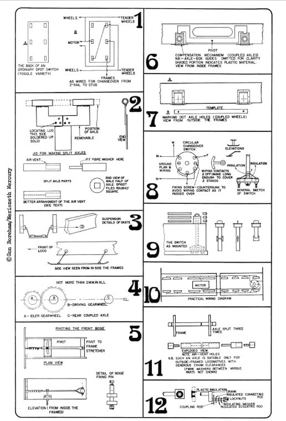
- As I have been convinced that two-rail is as efficient in this scale as in the smaller scales (a, belief strongly reinforced now that this model has done a good deal of running on the Model Railway Club's track), it is a two-rail job. But as I shall undoubtedly visit stud-worked layouts with it, it is stud as well, and converts at the turn of a switch (more of this later).
- It has split axles and picks up on all wheels, the eight wheels of the tender included. Now, when a tender locomotive is arranged for two-rail working, the usual idea is to insulate on the other side of the tender and use this fact to pick up current, feed it to the motor and return it to the track. Thus one uses half (or possibly less) of the available points of contact between locomotive and track, and I think this is foolish. Why waste half of your assets? You cannot have too many electrical paths if you want to be sure that your model gets a good, uninterrupted supply of current (without which it will not works) under all conceivable conditions, including less than perfectly clean track and wheels. So use all the wheels to pick up current. Indeed, I am thinking of applying this technique to the whole train.
- Non-driving axles are cut in half and forced into Tufnol sleeves in the usual manner. Driving axles - i.e., those accommodating the coupled wheels - are made as in Fig. 2B and C, in two halves. One half is drilled and the other has a protruding spigot which is a very sloppy fit in the tube. Also the spigot was filed roughly square to give the Araldite, which I used as bonding agent, a chance to grip. The Araldite is cured in a hot oven while the axle is in the jig, Fig. 2A. This comes apart, being held together by 10 BA bolts. Take it apart, insert the axle and take care not to let the Araldite touch the jig, or the whole assembly will be locked solid, jig and all, when the Araldite is cured. You will also need to drill a small hole in the female part of the axle to let out surplus air and Araldite. I personally drilled a hole at right angles to the main cavity, Fig. 2B(i), but I think that a better idea would be to drill a small hole right along the axle as in Fig. 2B(ii). In this way there is no danger that Araldite will seep out during curing and lock everything solid.
The jig is very easy to make. The two bits of tubing which hold the axle should be threaded onto a piece of the rod from which the axles are made, and soldered into place, afterwards withdrawing the rod. This ensures perfect alignment. I made mine from a bit of brass rod which I drilled to the right diameter. Needless to say the hole should be as tight a fit as possible and it would be worthwhile to have this done professionally if necessary. Once done, split axles are no problem at all to make; incidentally, the join in them should be about one-third of the way along, not in the middle, or your gear wheel will span it and cause a short circuit.
- Split axles usually mean split frames, but in this case the coupled wheels are compensated and the axle boxes slide up and down in the horns. The boxes are made of Tufnol and are bushed, wire being soldered to the bushes and led to the changeover switch and thence to the motor. Split frames are therefore not necessary.
- As the wheels are insulated from the frames, the stud contact skate, when fitted, does not need to bet It is merely sprung into its bushes and can be fitted or removed in a moment (Fig. 3). On a two-rail layout it would, of course, be removed or it would foul the points. However, the system does mean that on a stud line the locomotive body is at a different polarity from that of the rolling-stock - so the coupling bar (the Norwegian type is not used in Fiji) is insulated with a Tufnol or Bakelite insert.
- The motor is an ex-government Delco motor which I bought years and years ago for 12s 6d.: DC 27 volts, nine poles (or rather nine slots). It will run light on two volts and drive the locomotive on ten, so at present I restrict it to a maximum of about 15v, when its consumption when driving the locomotive without a train is a steady 2amp. i.e. its rating is only three watts.
- Gears. Gearing is 75:1 because the maximum permitted speed of the original is 15 m.p.h. (although we are told that she will do 18 m.p.h. downhill with a following wind). There is the small wheel on the same axle as the pinion and the large one on the same axle. As this latter can move up and down about 2 mm, the problem is how to keep the two plastic gears in mesh. Answer: both coupled axles and the idling axle must be in the same plane when in the normal running position. See Fig. 4.
- Suspension. As already stated the driving wheels are compensated. The horn blocks rest on a compensating bar which is pivoted half-way between them (Fig. 6). Normally they are kept there by the weight of the locomotive but are free to move if the track is irregular. In addition the front bogie is also compensated by being pivoted, in the centre of each side, to a piece of Tufnol rod, which also insulates each half from the other. A metal rod passes through a vertical central hole in the Tufnol rod and thence through a slotted stretcher in the frames, where it is pivoted - see Fig. 5 - the spring ensuring it always returns to the central position. As the bogie can also pivot round this central pin it is an Adams bogie, not a Bissel truck, which does not pivot round a central pin. The bogie also has Adams compensation bars on the outside but as it is fully compensated already it must be admitted that these, like the springs above the coupled wheels, are merely dummies.
- The tender (which, being carried on two bogies, is indistinguishable mechanically from a bogie carriage) has compensated bogies also. I do not anticipate many derailments from this machine.
- Quartering. I have long been of the opinion that the most difficult operation for anyone not in a position to use Romford quartered wheels and axles is to get the quartering right. (In fact, if I build many more locomotives in this scale I'm going to make a jig - it will be well worth the work involved.) As I said in "Narrow-Gauge Railway Modelling", one mistake here and the locomotive will not work. Normally it helps to solve this problem by cutting and drilling both frames at once, along with a template for the coupling-rods, since the most accurate quartering in the world is useless unless the distance between centres is exactly equal on both sides of the locomotive and also the coupling-rods.
These should be fitted and carefully blocked (to make it impossible to move them up or down while marking out is going on) at the central point of their up-and-down travel; then scribe a horizontal line across roughly the vertical centre line of both (set the dividers at the right distance apart using the straight top of the frame as a reference point then scribe the lines using this as a guide). Having done this, scribe a vertical line down the centre of the front box to cut a horizontal line (Fig. 7). Dill the hole using the same small drill that you used for drilling the template: leave the drill in the hole: place the template over it and adjust it against the rear hole in the template. Then mark the centre - you can do this by eye as the hole is small - and drill. Repeat on the other side of the locomotive. Then open the holes out to their final size and bush them. Then cut the two coupling-rods, using the same template to mark the centres. Start by drilling these two holes and then draw the coupling rods round them – it’s easier that way!
As this is an outside-framed machine the cranks will have to be added. These are cut and filed to shape and the two holes for the axle and crankpin are drilled, using the template as already described. Open out the axle-hole to a push fit and press it onto the axle. When in position a small hole (No. 54) is drilled through axle and crank combined, tapped and fitted with a 10 BA bolt. The protruding head of this can be unsightly, so before fitting this cut off the head and saw a slot across the top. This makes a satisfactory grub screw.
All this can be done on three of them straight away, adjustments being made on the fourth. Push this onto the axle, add the rods, twist back or forth until all runs sweetly, then drill and fix as before. That is how I quartered my axles. I'll make a jig next times
- Turnery. With one exception I did all thi3 myself and there is no doubt, firstly, that in this scale a small lathe is absolutely essential, and, secondly, that the ability to use the lathe efficiently is the line of demarcation between the model-basher and the model engineer - a line which I do not claim to have completely crossed. You might describe me as being stuck half-way over! The proof of this is that I do not yet consider myself sufficiently adept to machine wheel blanks, so, not wishing to spoil this model by badly made coupled wheels, I asked Brother Jim - some say Uncle Jim - otherwise G.J. Arming, brother of the Model Railway Club Chairman and a real wizard with the lathe, to turn them up for me. I would like to take this opportunity of thanking him for his absolutely essential and expert help, and I only wish that the rest of the model were as perfect as its coupled wheels.
The wheels of the tender and leading bogie are part of a job lot which I acquired years ago at a MRC Rummage Sale. They have now come in useful.
The one problem about the tender was whether to make up one bogie side and have four sides cast, or to make up the four sides separately. In the end I decided that the latter course would be quicker, especially as the design is practically identical with a 7mm. scale cast side by Messrs. K's. I more or less copied this in 16mm. scale and found brass sleeper-strip a great help. Of course, when it comes to making the train - the bogies of which are practically identical with those used on the railway at Bowaters - I shall make one side and have them cast from that: and it won't be a bad idea to start with this - then the coachwork can be done while waiting for the bogie sides.
- The changeover switch. I decided to put this in the tender as there was more room for it there than in the locomotive. Although in Fig. 1 I have given details of the circuit using a conventional double-throw switch I could not find anywhere to put it where it would be both inconspicuous and easy to get at, so I finally decided, most reluctantly, that I would have to make my own switch, of the circular variety. This is cut from Bakelite, the studs are 10 BA bolts, and the construction is shown in Figs. 8 and 9. It has stops to prevent it from moving too far and is wired as shown. Fortunately, the tender has a filler pipe and cap at the rear, and by siting the switch immediately below this I was able to arrange that by turning the cap the switch is operated - thus it is both effective, inconspicuous and easily available.
Fig. 10 shows the wiring. The practical difficulty here was what to use to "plug in" the locomotive to the tender. I found a small eight-pin radio plug and socket and cut this down, mounting the socket on the underside of the front of the tender. The four connecting wires from the locomotive are neatly encased in about 1 in. of grey plastic sleeving and all the wires and sleeving were rescued from the wastepaper basket after the GPO telephone engineers had visited my office to repair my telephone, which proverbially went wrong just then (no, I didn't sabotage it). There are now five pins on this plug, including a connection at present unused.
At the time of writing the headlight is a dummy, and represents an ordinary electric headlamp. The original headlamp, a photograph of which appears on p. 70 of "B.S.& S.C.", was a much larger and more elaborate affair, rather like the ones carried by the Leek and Manifold locomotives.
Returning to Fig. 10 it should be noted that although for simplicity's sake the electrical leads are there shown as being attached to the wheels (L) in fact the leads are soldered to the appropriate side of each bogie and in the case of the driving wheels to the metal bushes through which the axles pass.
It should also be noted that as the D.P.D.T. switch is in the tender the locomotive will not run without the latter. If for any reason (such as testing) it is necessary to run the locomotive on its own a little U-shaped plug will have to be made. This, when fitted into the right sockets, and make sure they are the right ones!, will short circuit the tender.
- Cylinders and valve-gear. Outside: Walschaert's. This presents no problems to anyone who has done similar work in smaller scales. In any case there is an excellent book on the subject - "Model Locomotive Valve Gears" by Martin Evans - which gives all the necessary advice. Until I read this I had not realised how many types of valve gears there are! So there is no problem here. What does present some difficulty, though, is the question of insulation since unless the valve-gear assembly is insulated at some point, it will form a bridge between the axles and frames and cause a dead short.
A third way - the one I chose - is to insulate the connecting rod and eccentric rod by means of a Tufnol or other insulating sleeve rather like the insulation on an 00 gauge wagon wheel. As it is easier to see than to describe, Fig. 12 will show you what I mean. It is not necessary to insulate the coupling rods. A further way would be to make the cranks of Tufnol - but I cannot say, not having tried it, how satisfactory this would look or be.
Superstructure. This is made in three main parts: cab, boiler and firebox, and smokebox. The boiler is of brass tube which was opened out at the firebox end. The smokebox and cab contain most of the solder used on this model (except for a little on the tender) and the rivets are pin heads. The cab contains a few fittings - reversing lever, regulator, brake, pressure gauge, whistle control gear, firebox doors, rear springs and (eventually) a sanding control lever. Its most unusual feature is, however, the double skinned roof, used in the tropics to help keep cabs cool. For the same reason the spectacle plate windows are nearly always left open - so they open on the model. The side windows are unglazed. The front end of the boiler is closed with a turned cap into which it fits. This then fits into the smokebox unit, and the two are held in position by a 6 BA bolt. So the smokebox does have to open for accessibility.